

Control Module with Integrated Driver for Stepper Motor – Performance and Precision in Industrial Automation
This control module with integrated driver is specially designed for single-axis stepper motors, providing a complete solution for industrial automation, CNC control, robotics, and mechanical packaging systems. It operates independently or in combination with other systems, without requiring Arduino or Python, making it ideal for industrial control applications and precise stepper motor positioning.
Main Features
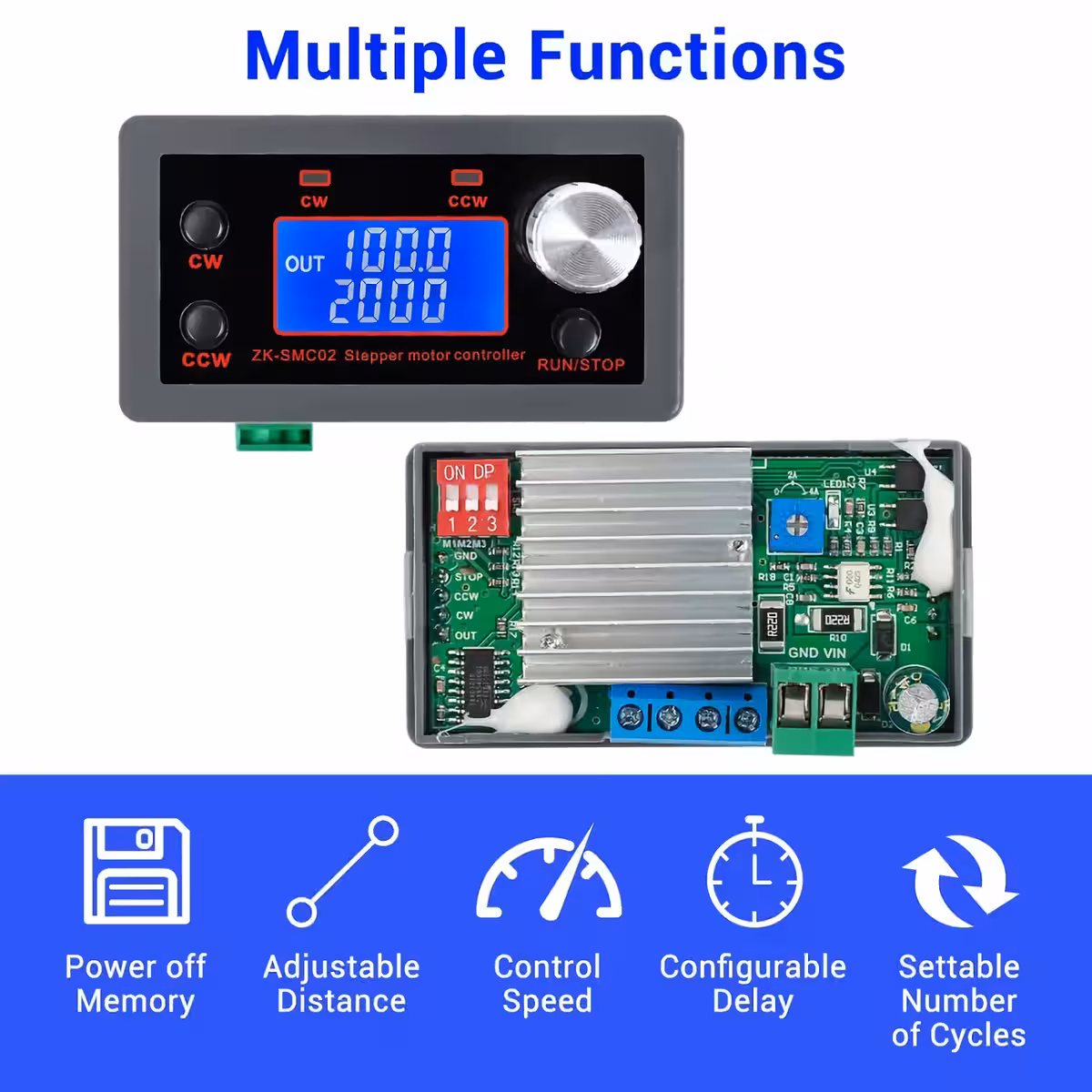
- Integrated Controller and Driver: Manages stepper motor control and monitors operating status in real time.
- Forward and Reverse Rotation: Change rotation direction via button or potentiometer, automatic depending on the working mode.
- 3 Control Modes: Preset mode, external button control, or additional driver control.
- 9 Work Programs: Includes programs for various applications: Forward/Backward, Delay, Loops, Auto Lock, Rotation Speed, and more.
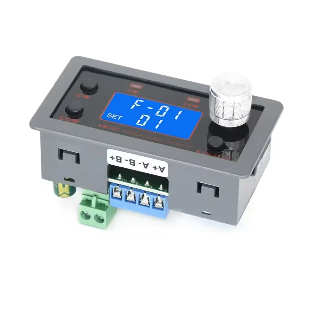
- HD LCD Display: Shows speed, number of cycles, and control parameters, with memory function and high precision.
Technical Parameters
- Input Voltage: DC 5V-30V
- Output Current/Driver: 4A (max)
- Control Axes: Single axis
- Compatible Motors: Stepper 42/57 (Nema17 / Nema23)
- Control Speed: 0.1-999 RPM
- Number of Forward Pulses: 1-9,999,999
- Number of Cycles: 1-9,999 or infinite loop
- Forward/Backward Delay: 0.0-999.9 seconds
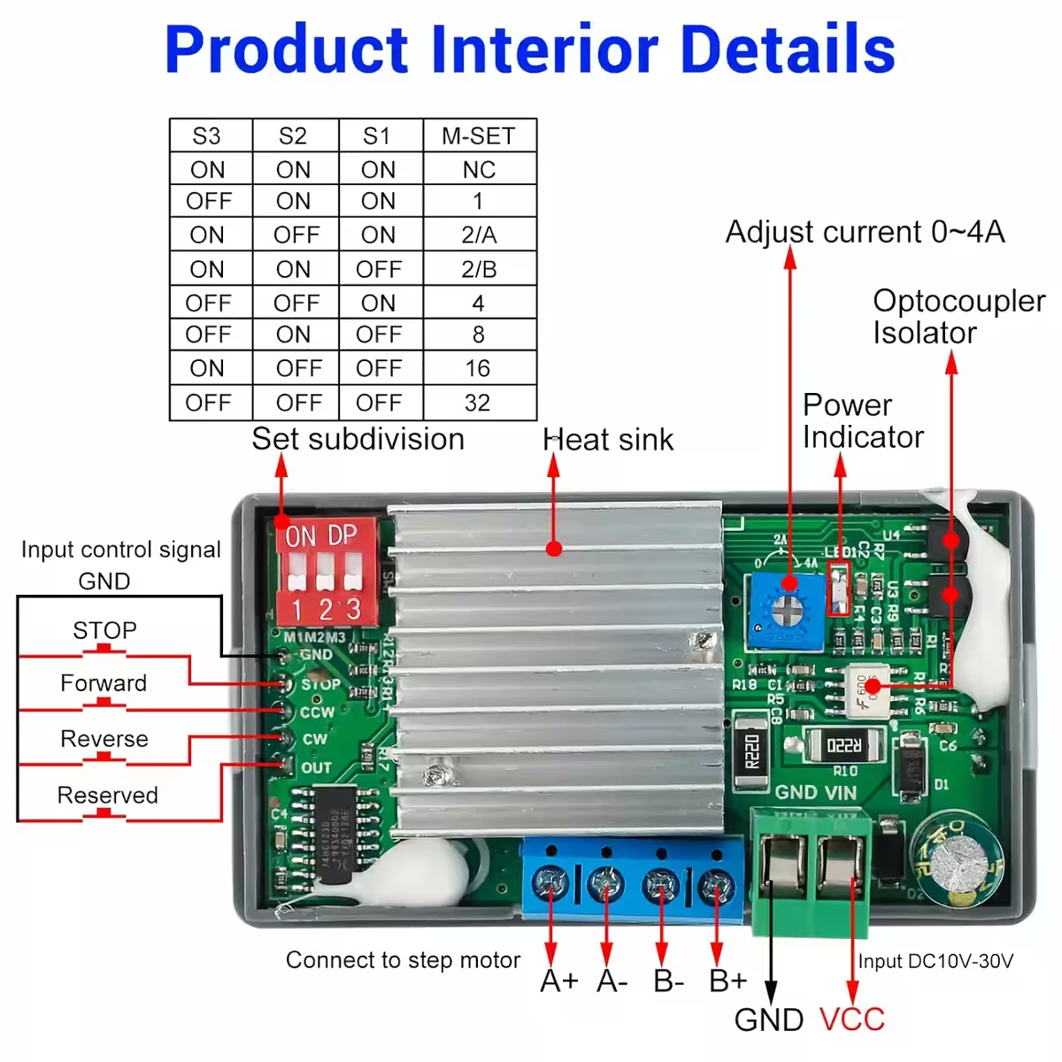
- Microstepping: 1/2/4/8/16/32
- Acceleration/Deceleration Control: Yes
- Input Reverse Polarity Protection: Yes
- Control Modes: Automatic/Manual/Setup
- Operating Temperature: -20°C to 85°C
- Operating Humidity: 5% to 95% RH
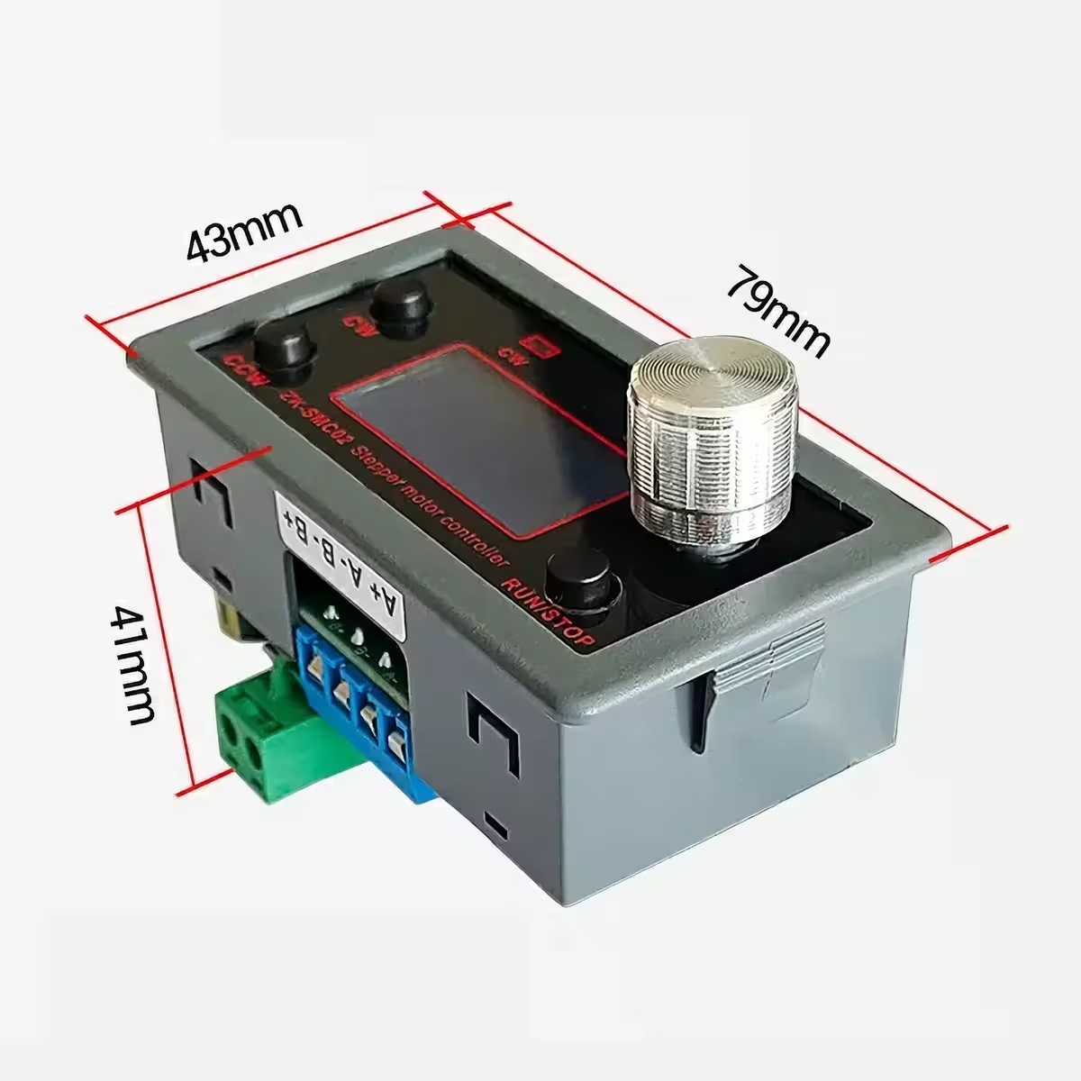
- Module Dimensions: 79 x 43 x 41 mm
Configuration Methods
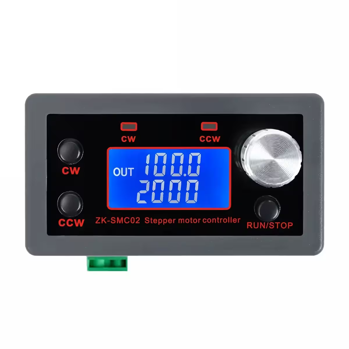
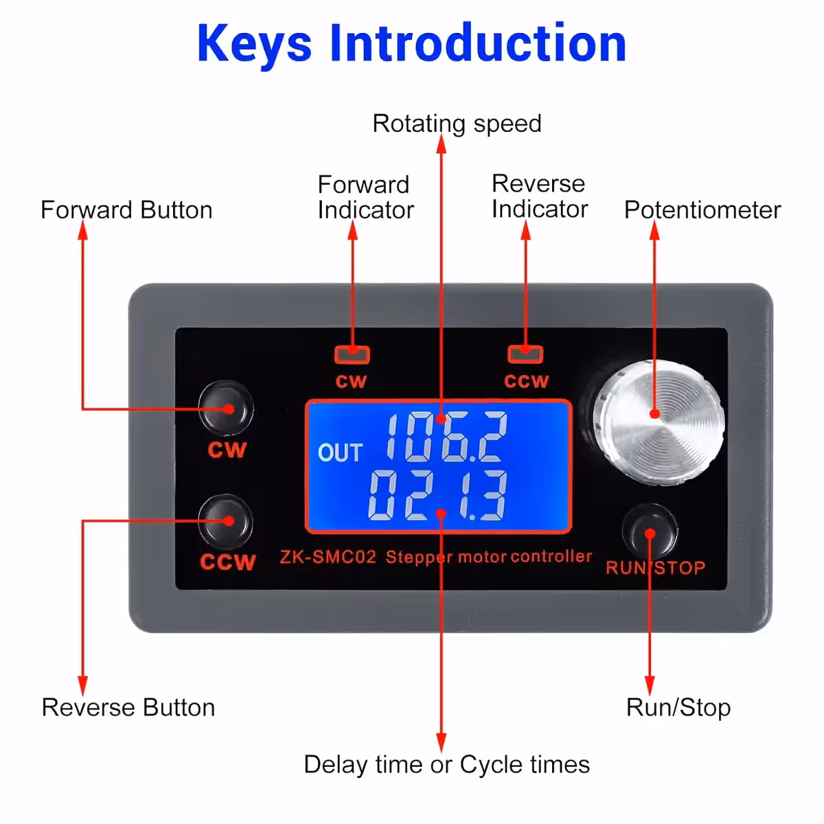
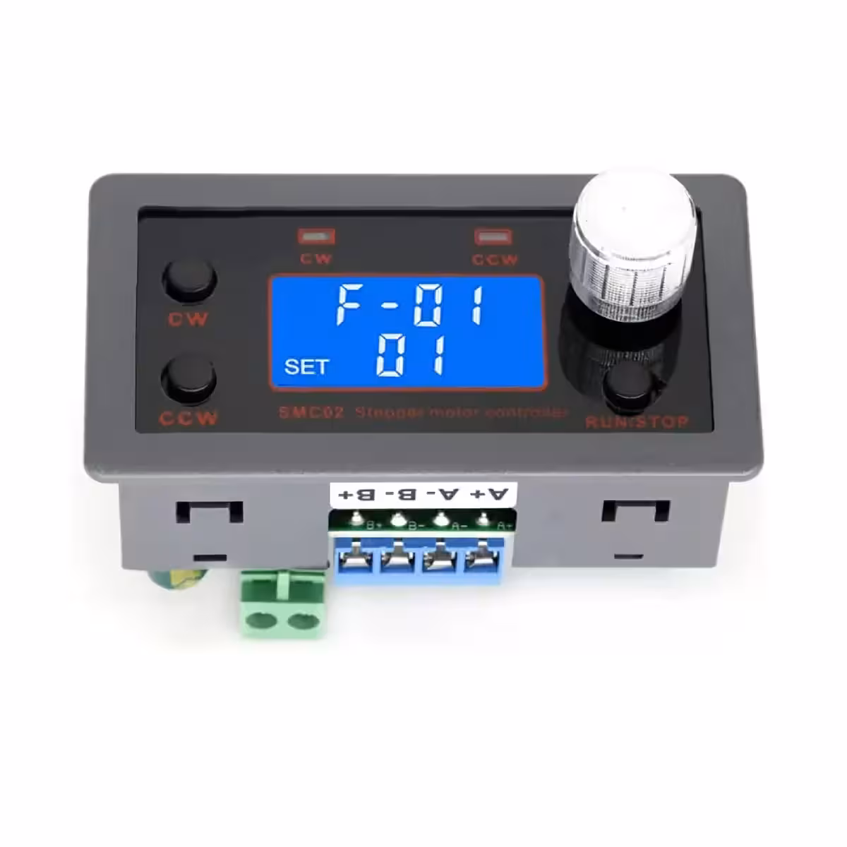
1. Running Interface
- The first line displays rotation speed in RPM.
- The second line shows delay time or number of cycles, adjustable via the F-10 menu.
- CW Button: rotate forward.
- CCW Button: rotate backward.
- RUN/STOP Button: start/stop.
- Potentiometer: adjust speed in both directions.
- Hold potentiometer >3 seconds: enter parameter setting mode.
2. Parameter Interface
- Rotate the potentiometer to select parameter F-01~F-13.
- The selected parameter blinks.
- Pressing the potentiometer selects the value.
- Change the value by rotating the potentiometer or selecting bits.
- RUN/STOP button confirms the parameters.
- Save and exit setting mode after >3 seconds.
3. Auxiliary Function
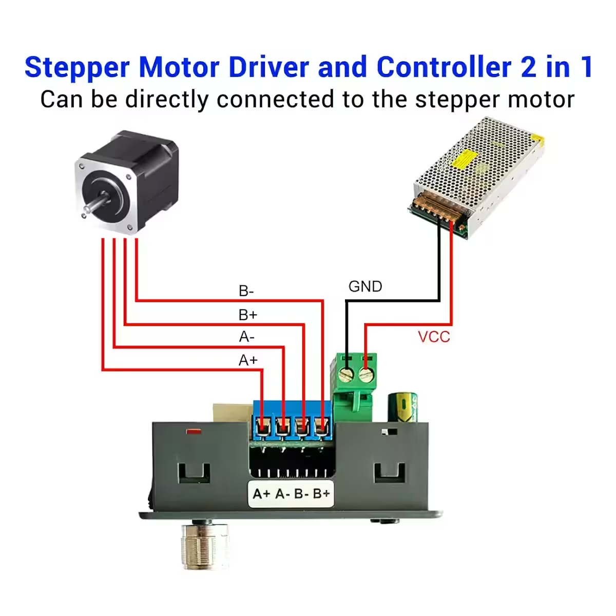
- Operates independently by connecting only power and motor.
- External buttons can be connected for additional control.
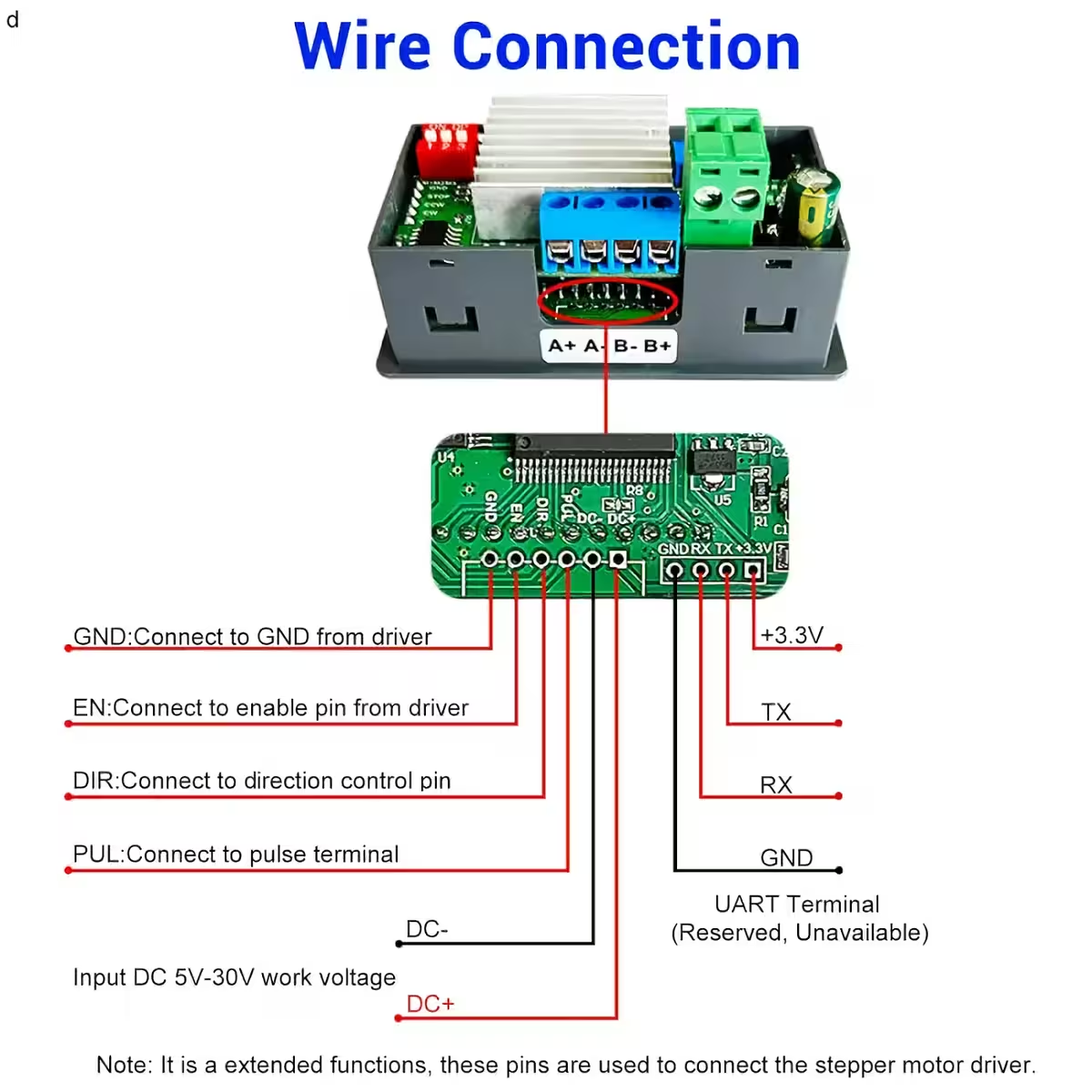
- Compatible with other stepper motor drivers – Auto/Manual/Setup mode.
4. Working Mode
- Automatic Control Mode: operates with set parameters.
- Manual Control Mode: requires connection of buttons to COM/STOP/CCW/CW terminals.
- Setup Mode: connect to other stepper motor drivers.
Important Notes
- Compatible with 2-phase stepper motors, regardless of wire count (4, 5, 6, or 8 wires).
- Includes integrated drivers and controllers but can also be connected to other external drivers.
Applications
- Industrial automated control
- CNC machines
- Mechanical packaging
- Electronics processing and testing
- Automatic assembly lines
- Robotics and process automation
- Positioning and motion systems
| Parameter | Function | Setting Range | Default Value |
|---|---|---|---|
| F-01 → ? | Select working mode. See the next table. | P01~P09 | P01 |
| F-02 | Number of forward pulses. Change High/Low bits by pressing potentiometer: High 3Bit: Hxxx, Low 4Bit: xxxx | 1~9,999,999 | 1600 |
| F-03 | Forward rotation speed in RPM | 0.1~999.9 | 10 |
| F-04 | Number of backward pulses. Change High/Low bits by pressing potentiometer: High 3Bit: Hxxx, Low 4Bit: xxxx | 1~9,999,999 | 1600 |
| F-05 | Backward rotation speed in RPM | 0.1~999.9 | 10 |
| F-06 | Number of work cycles (‘—-’ means infinite loop) | 0~9999 or infinite loop | 1 |
| F-07 | Forward movement delay in seconds. ±0.2s | 0.0~999.9 | 0 |
| F-08 | Backward movement delay in seconds. ±0.2s | 0.0~999.9 | 0 |
| F-09 | Number of pulses per rotation. Unit = 10. For example, if step angle = 1.8° and subdivision = 8, pulses per rotation = 360/1.8*8 = 1600. Set value should be 160. | 1~9999 | 160 |
| F-10 | Set LCD display parameters: 0: First line shows motor RPM, second line shows delay time in seconds. 1: First line shows motor RPM, second line shows number of cycles. | 0 or 1 | 0 |
| F-11 | Set motor behavior after RUN/STOP: 0: Slow down and stop. 1: Stop immediately. | 0 or 1 | 0 |
| F-12 | Set acceleration/deceleration level: 001 = slowest, 100 = fastest. | 001~100 | 20 |
| F-13 | Set device address | 001~255 | 1 |
| Working Mode | Operation Process |
|---|---|
| F-01 → P01 |
1. Motor operates with potentiometer rotation. Other buttons inactive. 2. Motor rotates forward and CW indicator lights if potentiometer turned clockwise. 3. Motor rotates backward and CCW indicator lights if potentiometer turned counterclockwise. |
| F-01 → P02 |
1. Motor rotates according to pulses set in F-02 and F-04. 2. Motor stops after each pulse set and can be reset with potentiometer. 3. Loop repeats according to cycle number defined in F-06. |
| F-01 → P03 |
1. Motor alternates rotation and stop according to defined pulses. 2. Forward/backward direction set by F-02/F-04. 3. Reset speed using potentiometer. 4. Note: Stop motor before changing direction. |
| F-01 → P04 |
1. Motor rotates from F-02/F-04 and stops, then repeats loop F-06 times. 2. Forward: F-02 → stop F-07 → loop. 3. Backward: F-04 → stop F-08 → loop. 4. Reset RPM with potentiometer. 5. Note: Stop motor before changing direction. |
| F-01 → P05 |
1. Motor rotates from F-02/F-04, then reverses and repeats loop F-06 times. 2. Forward: F-02 → stop F-07 → loop → reverse. 3. Backward: F-04 → stop F-08 → loop → reverse. 4. Reset RPM with potentiometer. 5. Note: Stop motor before changing direction. |
| F-01 → P06 |
1. Motor rotates from F-02/F-04, then changes direction and repeats loop F-06 times. 2. Forward: F-02 → stop F-07 → reverse F-04 → stop F-08 → loop. 3. Backward: F-04 → stop F-08 → reverse F-02 → stop F-07 → loop. 4. Reset RPM with potentiometer. 5. Note: Stop motor before changing direction. |
| F-01 → P07 |
1. Motor rotates according to pulses and returns to start in opposite direction. 2. Forward: F-02 → stop F-07 → return. 3. Backward: F-04 → stop F-08 → return. 4. Reset RPM with potentiometer. |
| F-01 → P08 |
1. Motor rotates based on delay time F-07/F-08 and stops, then loop F-06 times. 2. Forward: F-07 → stop F-08 → loop. 3. Backward: F-08 → stop F-07 → loop. 4. Reset RPM with potentiometer. 5. Note: Stop motor before changing direction. |
| F-01 → P09 |
1. Motor rotates forward from F-02, stops for F-07, then rotates backward from F-04 and stops for F-08, loop repeats F-06 times. 2. Reset RPM with potentiometer. 3. Note: Stop motor before changing direction. |


Reviews
There are no reviews yet.