


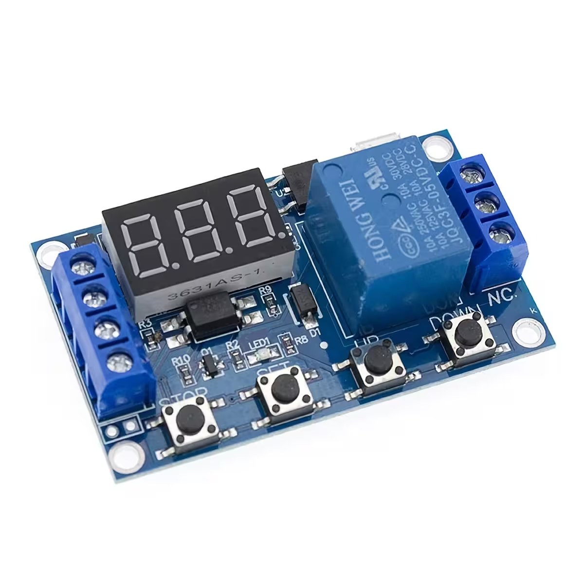
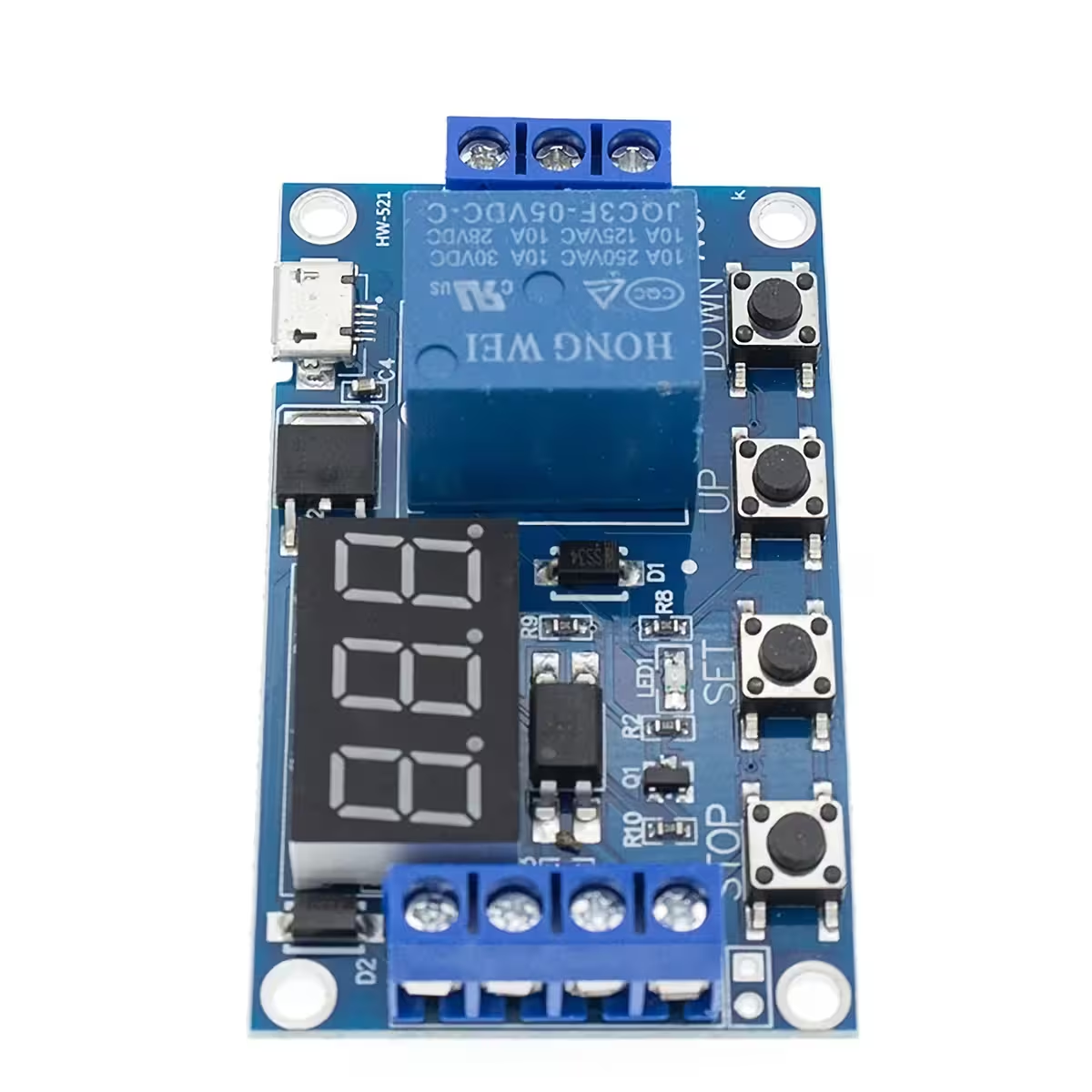
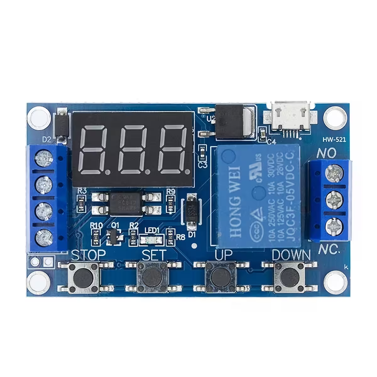
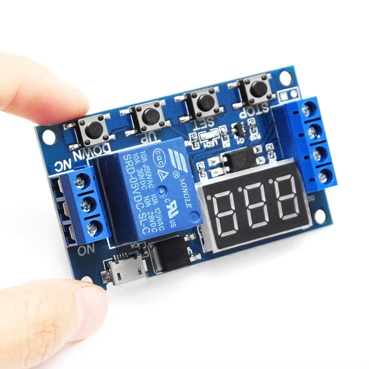
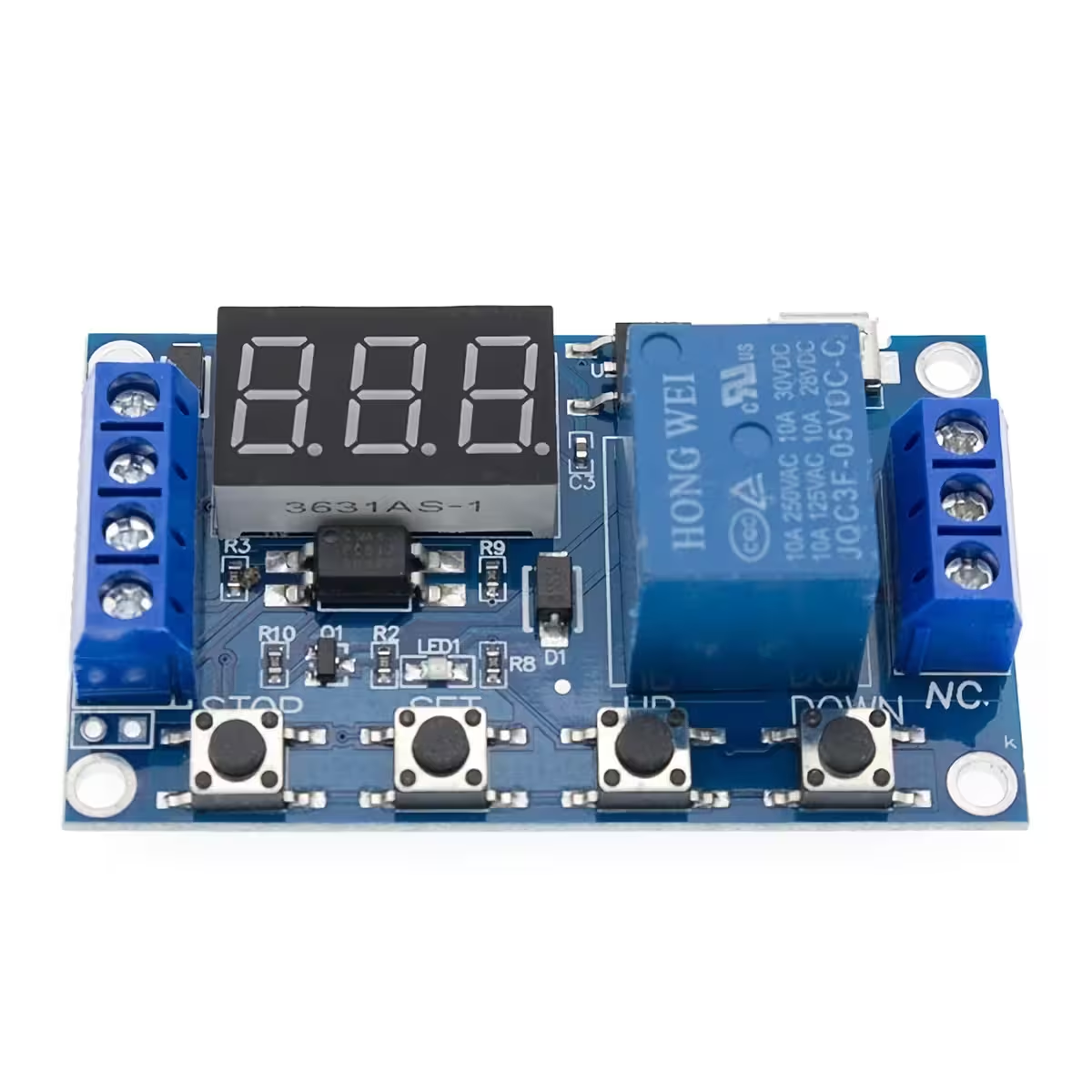
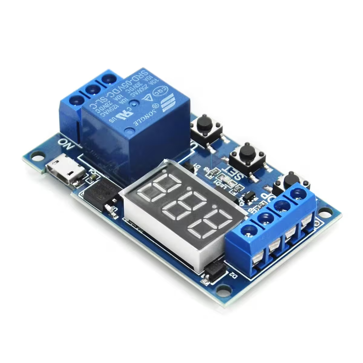
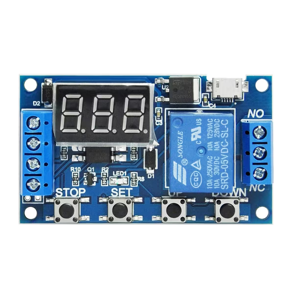
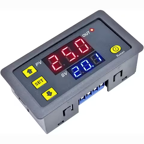
Programmable Timer Relay Module with Display — Precise switching from 0.1 seconds to 999 minutes
Need to trigger a pump exactly 30 seconds after a signal, cycle a ventilation system at fixed intervals, or generate a precise pulse from your Arduino? Without a dedicated timer, you often end up with unreliable, makeshift solutions. This programmable timer relay module with a built-in display solves this instantly, offering four configurable modes and an adjustable time range from 0.1 seconds up to 999 minutes.
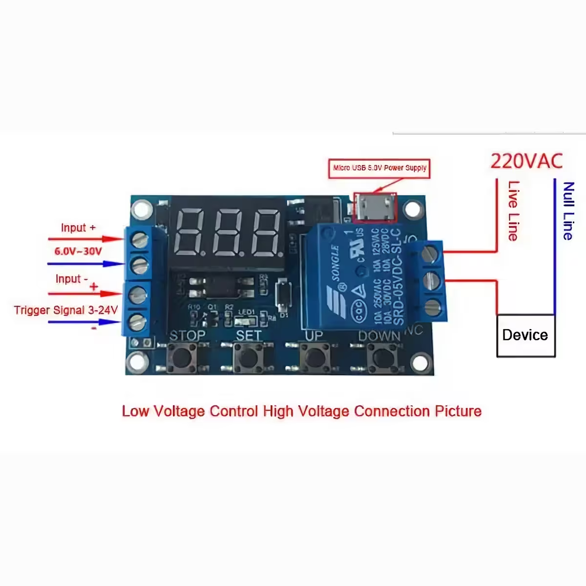
Note: The relay contacts are passive and exposed. Wiring to 220VAC mains voltage should only be carried out by a qualified professional.
Why choose this model? (Key Advantages):
- Optocoupler isolation — The control circuit and power circuit are completely electrically separated, protecting your Arduino or PLC from voltage spikes caused by inductive loads.
- 4 Operating modes (P1–P4) — From a simple fixed-duration pulse to repetitive ON/OFF cycles with a configurable number of repetitions, all without needing extra code.
- Selectable time resolution — Switch between 0.1s, 1s, and 1min increments with a single button press, without needing to reset your other settings.
- Digital display with bi-directional counting — View real-time countdowns or elapsed time, plus a clear relay status indicator.
- Non-volatile memory — All settings are saved automatically, ensuring your configuration remains intact after power cycles.
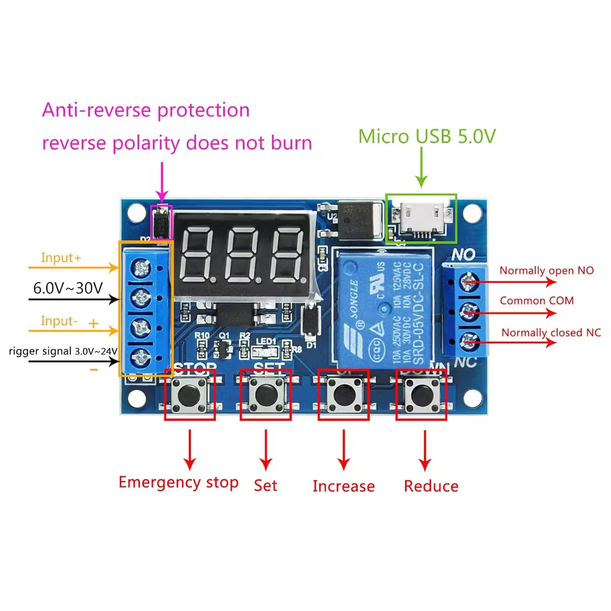
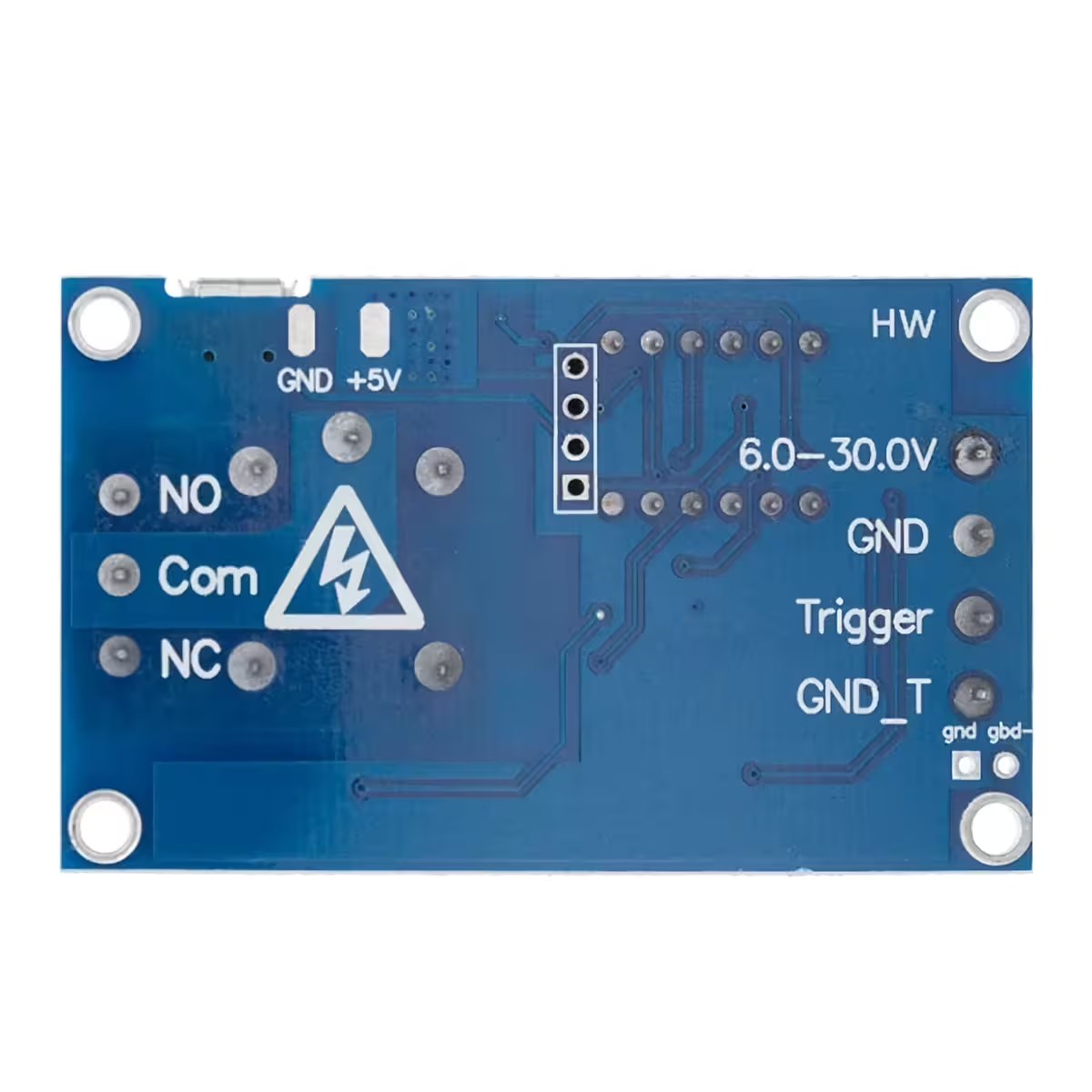
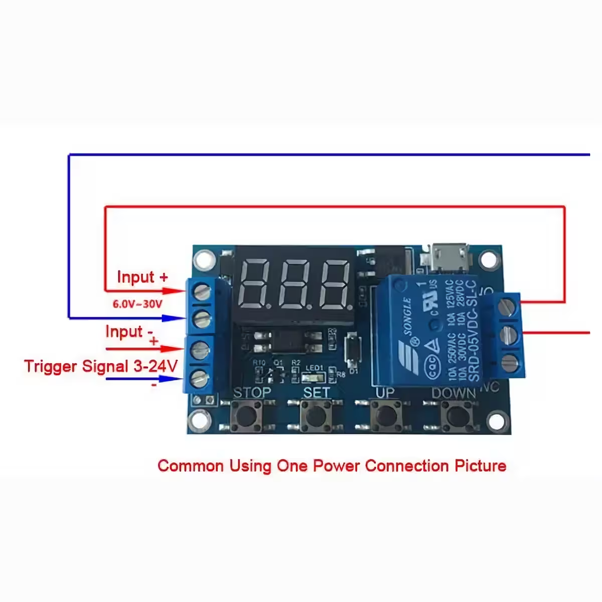
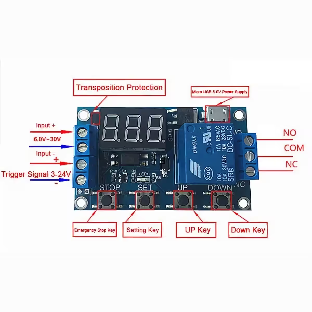
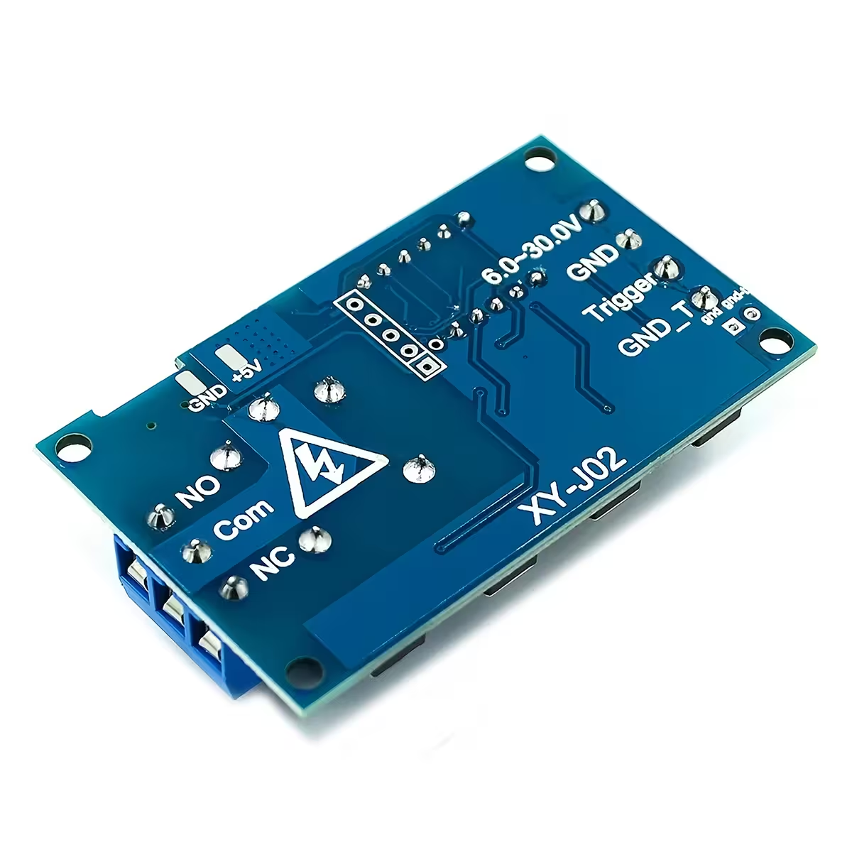
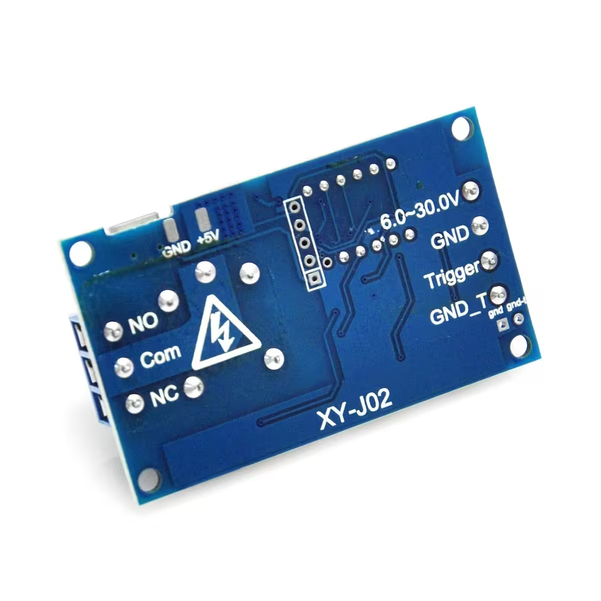
- Dual power input — Connect via 5V MicroUSB (perfect for power banks or chargers) or use the 6–30V DC terminals for industrial panel integration.
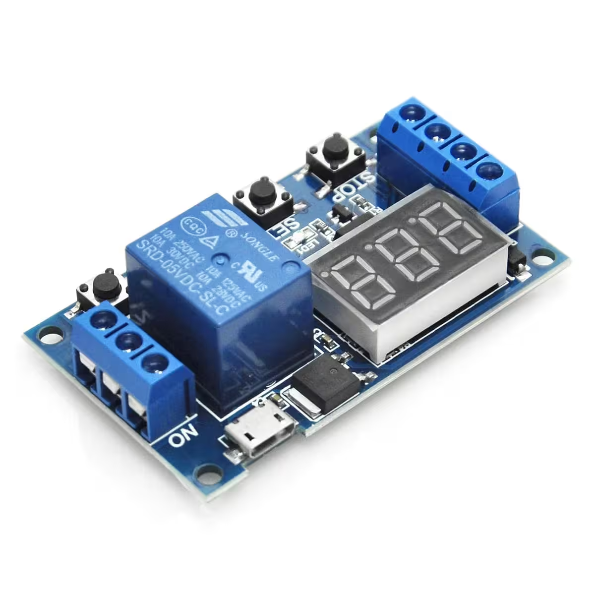
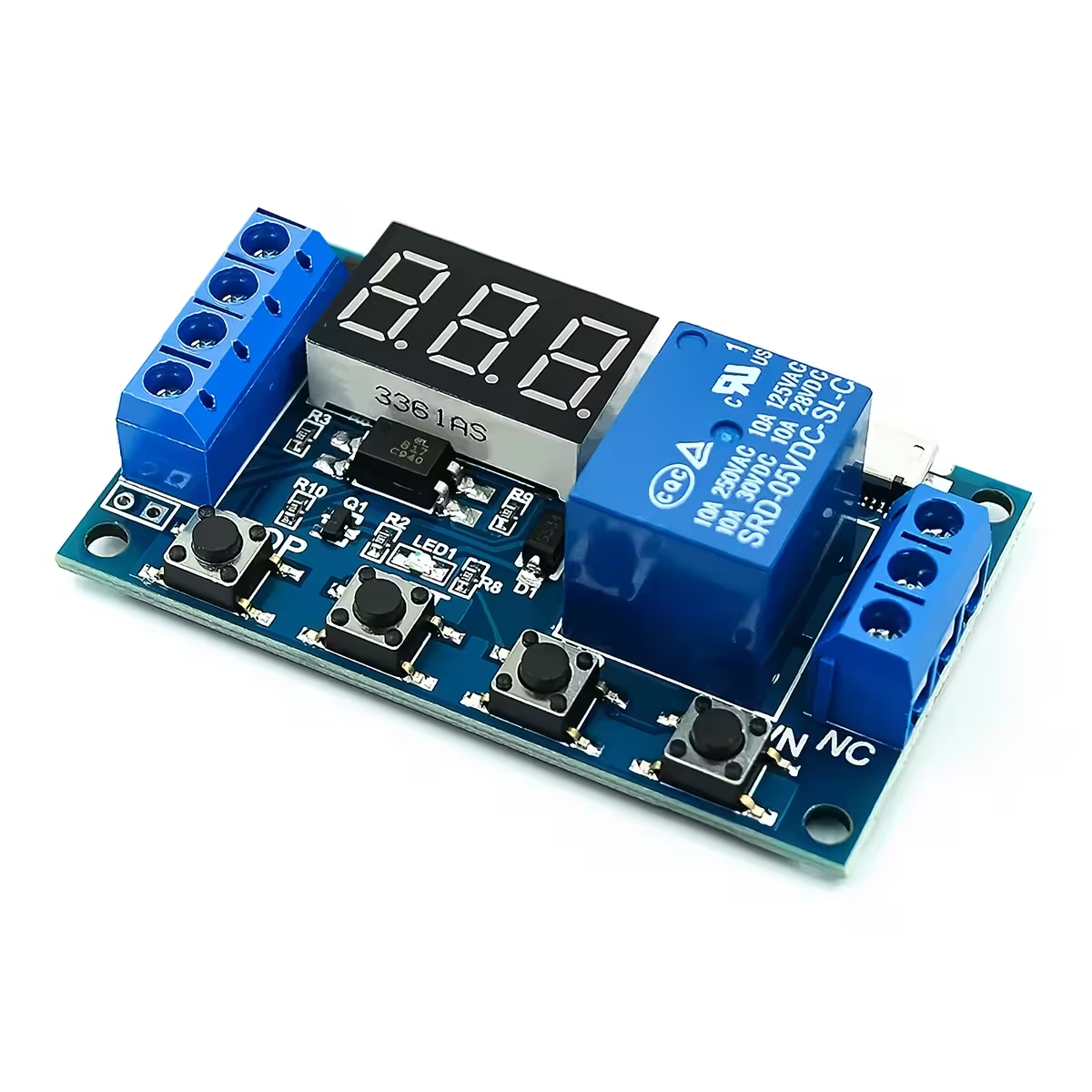
- Compact design (62 × 38 × 17 mm) — Fits easily into any DIY project enclosure or control panel without taking up unnecessary space.
Performance and Specifications
The 5A relay handles loads up to 30V DC or 220V AC — ideal for small motors, pumps, solenoid valves, or medium-power household appliances. The optocoupler isolation is a game-changer in electrically noisy environments, ensuring your microcontroller remains shielded from voltage spikes generated by the switched load.
The four programmable modes (P1–P4) cover a wide range of scenarios without requiring external logic. The LOP parameter in P3 mode controls the number of ON/OFF cycles — set it to 0 for infinite looping. The STOP button acts as an instant emergency stop, regardless of the timer’s current state.
| Parameter | Value / Detail |
|---|---|
| Supply Voltage | 5V MicroUSB or 6–30V DC via terminals |
| Trigger Signal | High Level 3–24V DC |
| Isolation Type | Optocoupler |
| Max Switching Current | 5A at 30V DC or 220V AC |
| Adjustable Time Range | 0.1 s – 999 min |
| Selectable Resolution | 0.1 s / 1 s / 1 min (via decimal point) |
| Operating Modes | P1 – Pulse ON, P2 – Delay then ON, P3 – Loop ON/OFF, P4 – Hold then Delay |
| Display | Digital, count-up / count-down + relay status indicator |
| Memory | Non-volatile (retained after power loss) |
| Control Buttons | SET / UP / DOWN / STOP |
| Dimensions | 62 × 38 × 17 mm |
Programming and Usage Instructions
- Connect power: Use the 5V MicroUSB port or the 6–30V DC terminals. The display will light up immediately.
- Press and hold the SET button for 2 seconds to enter the mode selection menu.
- Use the UP and DOWN buttons to navigate between modes P1, P2, P3, and P4. Briefly press SET to access the parameters for your chosen mode (OP, CL, LOP).
- To change the time resolution, press the STOP button while in the setting menu — the decimal point will shift between 0.1s / 1s / 1min. Example: 03.2 represents 3.2 seconds.
- Once your values are set, hold SET for 2 seconds to save the configuration and return to the main screen. Parameters are stored permanently.
- The STOP button on the main screen toggles the relay ON/OFF and functions as an emergency stop at any time.
Package Contents
- 1× Programmable timer relay module with digital display
- Terminal blocks for power and relay output (pre-mounted)
- MicroUSB port for 5V alternative power
Frequently Asked Questions
Can I power the module directly from a power bank via MicroUSB?
Yes. The MicroUSB port operates at standard 5V, making it compatible with any power bank or phone charger. This is particularly useful for portable DIY projects or quick bench testing.
What loads can the relay safely switch?
The relay supports up to 5A at 30V DC or 220V AC. For motors or pumps with high inrush currents, we recommend using an external contactor; the module’s relay then acts as the control signal rather than carrying the full load directly.
Can a 3.3V pin from an ESP32 trigger the module?
Yes. The trigger input accepts High Level signals between 3V and 24V DC, so digital pins from an Arduino, ESP32, or Raspberry Pi will activate the module directly without extra resistors or circuits.
What happens to my settings if the power cuts out?
Nothing is lost. The module features non-volatile memory, meaning your selected mode, OP and CL times, and LOP cycle counts remain saved regardless of power interruptions.
How does P3 mode work and can I limit the cycles?
P3 mode executes a repeated automatic ON/OFF cycle. The LOP parameter sets the number of repetitions — set to 0, the cycle runs indefinitely. P3.1 triggers via an external signal, while P3.2 starts automatically upon power-up without needing a trigger.
Reviews
There are no reviews yet.