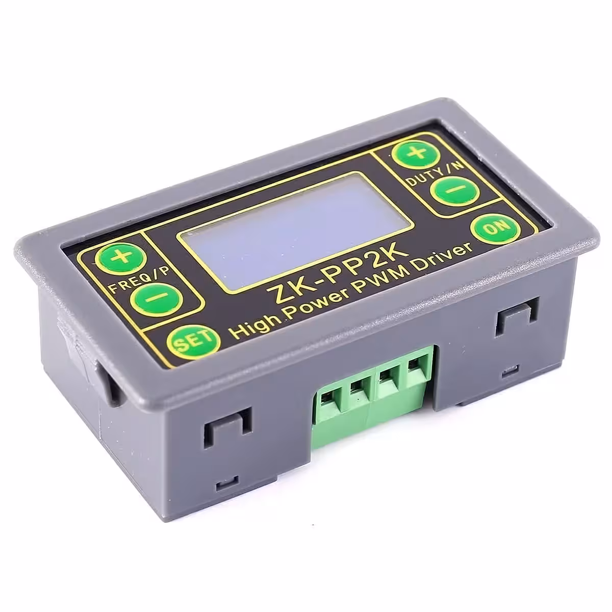
This device represents a cutting-edge solution in the industry, providing a wide range of electrical signals, including square waves, pulses, and adjustable output levels. With its dual PWM and PULSE modes, it offers versatility in signal modulation, meeting diverse testing requirements across various industrial sectors.
Equipped with state-of-the-art technology, this device offers unprecedented functionalities, making it an essential tool for applications such as experimental development, motor control, microcontroller interfacing, brightness adjustment, and speed control.
Technical Specifications
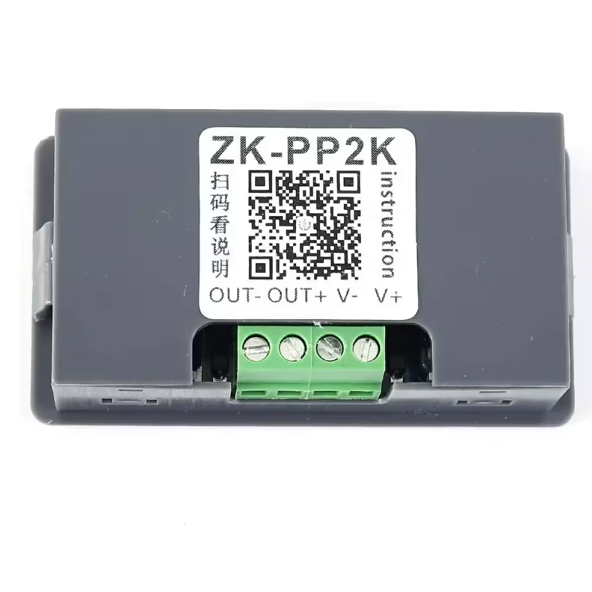
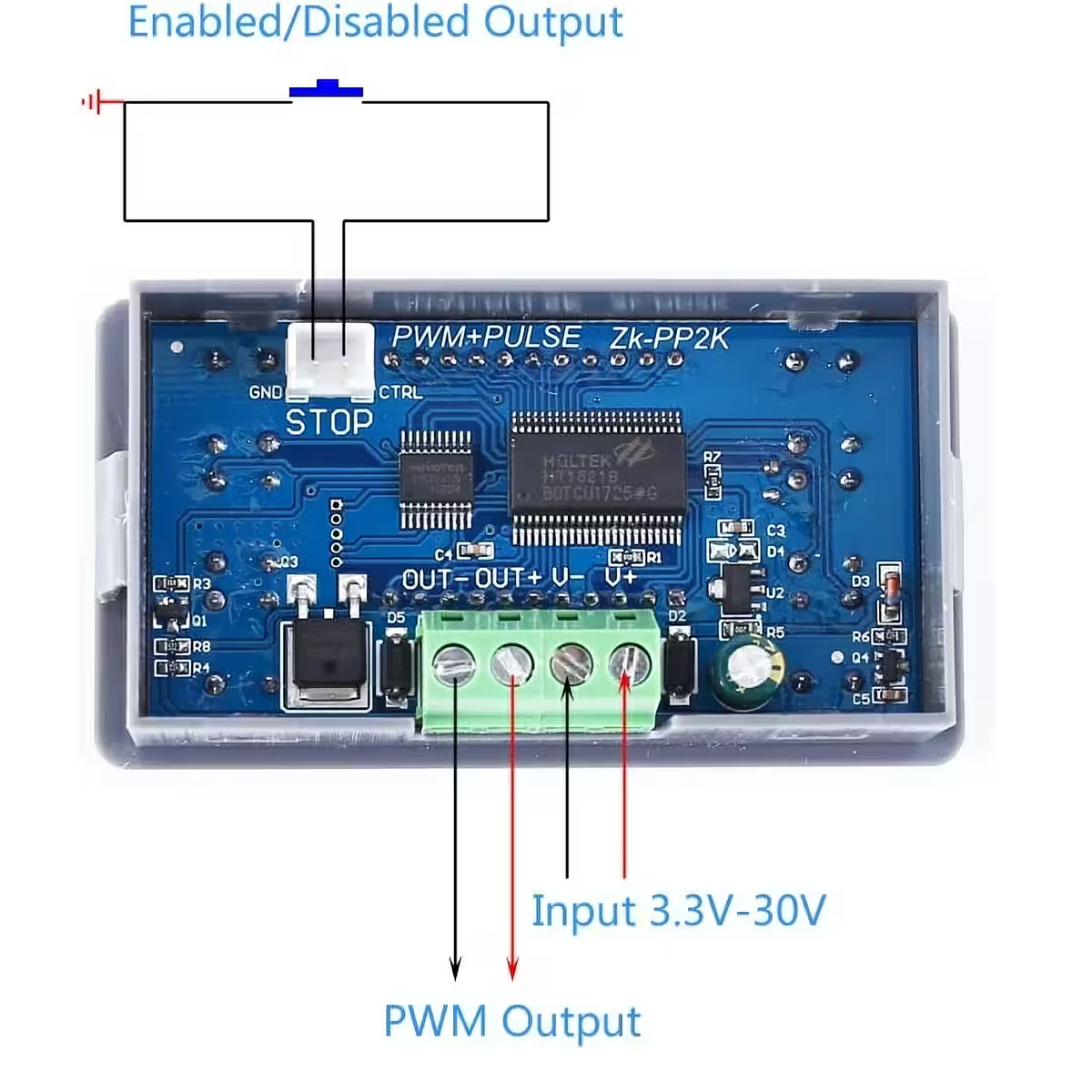
Operating Voltage: DC 3.3V-30V
Frequency Range: 1Hz~150KHz
Duty Cycle Range: 0.00%-100%
Output Current: Up to 8A
Number of Pulses: 1~9999 or Infinite
Delay Time: 0.000s~9999s
Operating Temperature Range: -20℃~85℃
Operating Humidity Range: 0%~95%RH
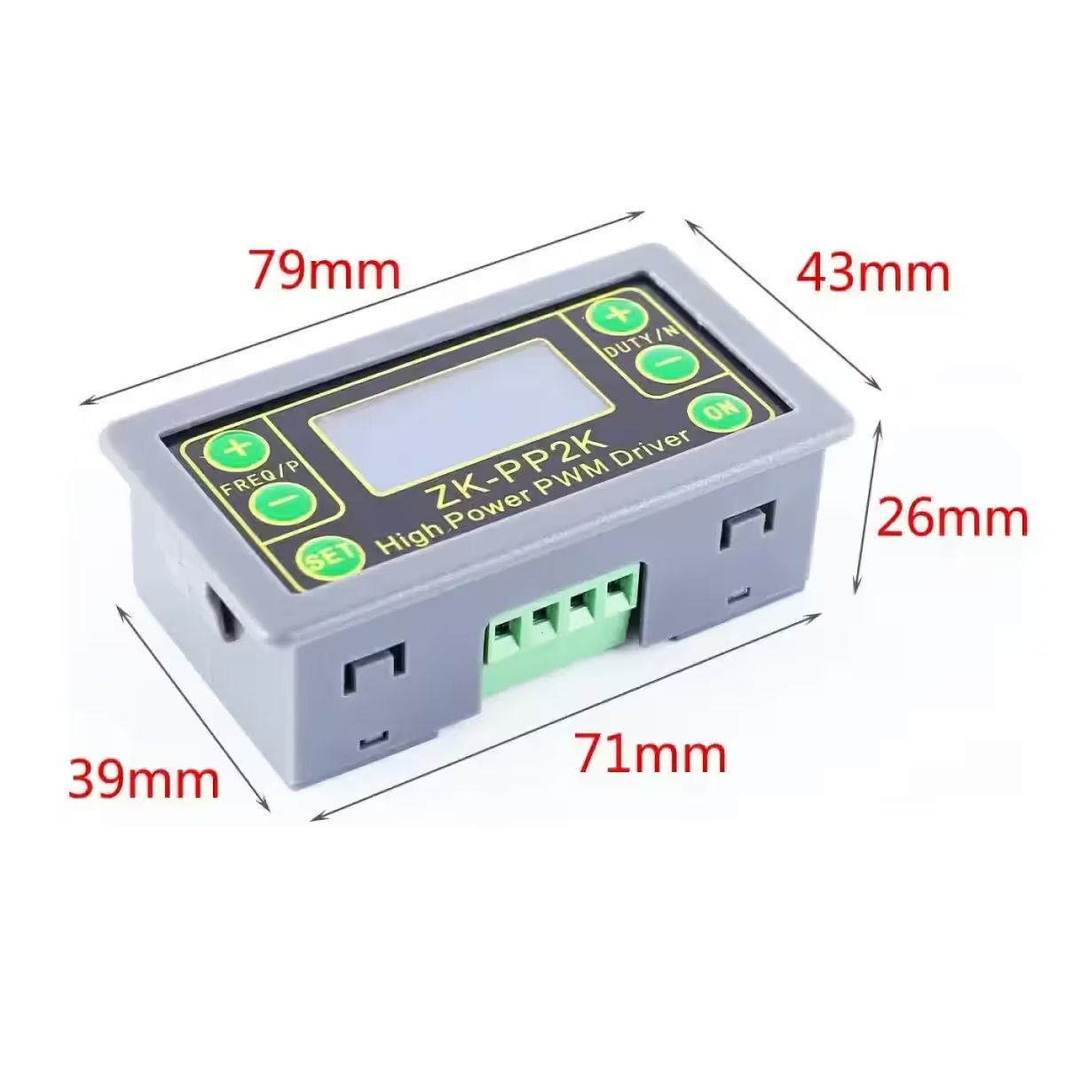
Dimensions: 79 x 43 x 26mm
Operating Modes:
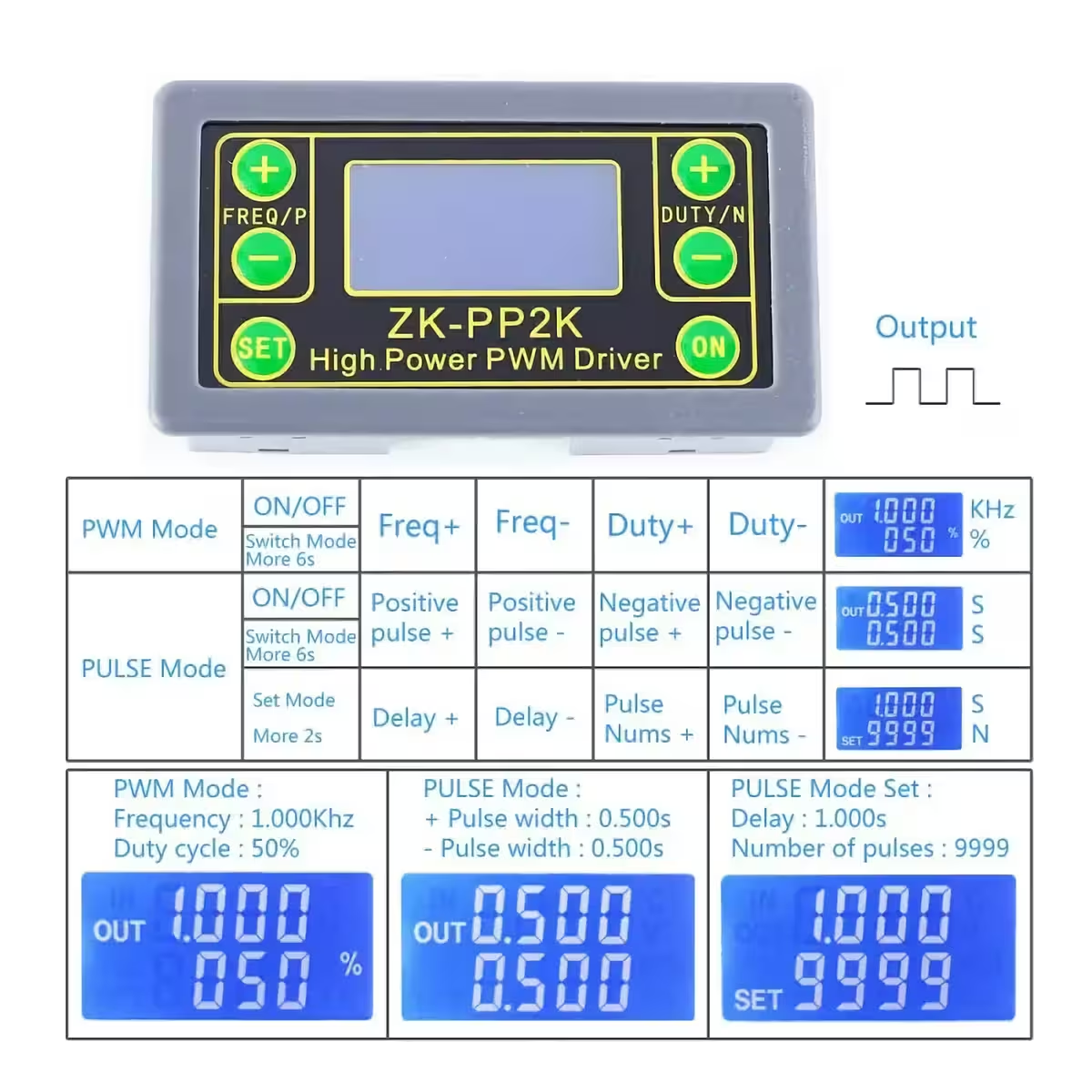
1. PWM Mode: Frequency, Duty Cycle
Adjust the frequency (from 1Hz to 150KHz)
Adjust the duty cycle (from 1% to 100%)
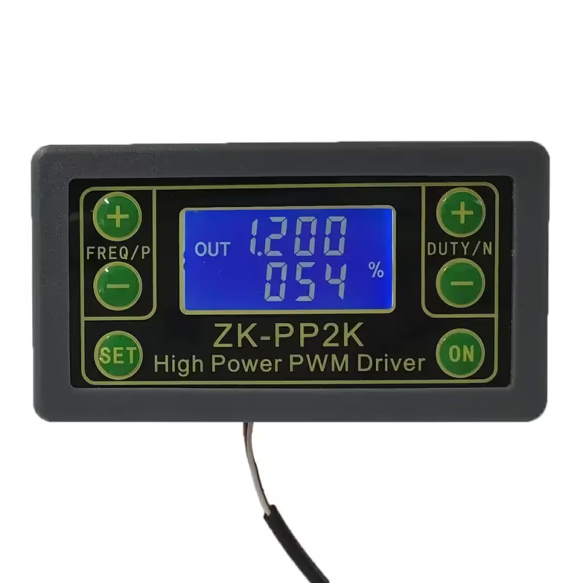
This is PWM mode when the ‘%’ symbol is displayed.
The factory default mode is PWM mode.
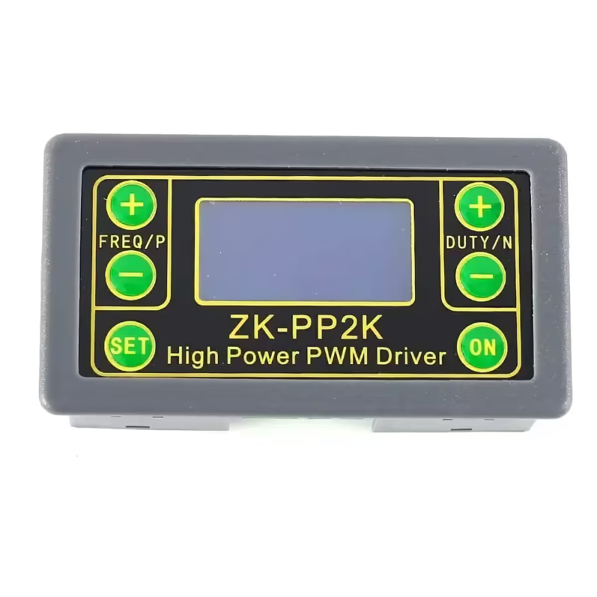
The FREQ+ and FREQ- buttons are used to set the output frequency. Short press sets the value in the minimum unit, long press sets continuously. Frequency range: 1Hz to 150KHz.
The DUTY+ and DUTY- buttons are used to set the duty cycle for the signal. Short press sets the value in the minimum unit, long press sets continuously. Duty cycle range: 0.00% to 100%.
Short press the ‘ON’ button to turn the output on or off. Output is active when ‘OUT’ appears on the left. Output is off if ‘OUT’ does not appear, and the module will produce 0V.
Factory default frequency: 1KHz, duty cycle: 50%.
To switch operating mode: Hold ‘SET’ for about 6 seconds. Enter PULSE mode if the ‘%’ symbol disappears on the right.
2. PULSE Mode: Pulse Width, Delay, Number of Pulses
Customize positive and negative pulse widths
Cyclic timer with relay (ON/OFF duration between 0.0001 and 9999 seconds)
Configurable start delay (0.0001 – 9999 seconds)
Number of pulses: 1 – 9999 or Unlimited
This is PULSE mode without the ‘%’ symbol displayed.
P+ and P- buttons set the positive pulse time on the first line. Time range: 0.000s to 9999s.
N+ and N- buttons set the negative pulse width on the second line. Time range: 0.000s to 9999s.
Short press ‘ON’ to activate or deactivate output. Output is active when ‘OUT’ appears on the left. Output is off if ‘OUT’ does not appear, module produces 0V.
Hold ‘SET’ for 2 seconds to enter pulse count and delay settings. ‘SET’ appears at the bottom-left. Note: Output will be disabled and pulse count cleared in this mode.
P+ and P- set delay time. Range: 0.000s to 9999s.
N+ and N- set number of pulses. Range: 1 to 9999 or Infinite (‘—-‘).
Factory default delay: 0s, pulse count: Infinite.
Return to pulse interface by holding ‘SET’ for 2 seconds.
Short press ‘ON’ after setting delay to start generating the set number of pulses.
Output automatically produces 0V if pulse count reaches the set value. Press ‘ON’ during output to reset.
Set pulse count is generated each time the module is powered on and stops, or ‘ON’ is pressed to restart.
Practical Application Ideas for a Motor:
Generate a 20KHz square wave with 60% duty cycle in PWM mode.
Create an infinite cycle with 0.6s ACTIVE and 0.2s INACTIVE pulses in PULSE mode.
Implement a 5s delay after start, then run a cycle with 0.6s ACTIVE and 0.2s INACTIVE pulses.
Set a 5s delay after start, then 10ms ACTIVE and 10ms INACTIVE pulses repeated 100 times.
5s delay after start, then maintain continuous output.
Usage Ideas:
DC motor speed control in fans, RC vehicles, and other electric motor devices.
Precise stepper motor control in 3D printers, robots, positioning systems.
Servo motors and actuator control in industrial robotics.
LED brightness control in lighting applications.
Solenoid valve control in irrigation systems and other industrial uses.
Testing and calibration of temperature or light sensors.
Simulating sensor signals for electronic testing.
Audio applications: testing and calibrating audio equipment.
Generating remote control signals for drone or RC testing.
Calibrating electronic devices: oscilloscope, multimeter, etc.
Experimental development: circuit testing in labs.
Educational experiments in schools and universities.
Hobby projects: electronic games, art installations, IoT devices.
These examples demonstrate the device’s versatility and applicability across a wide range of fields, providing precision and ingenuity in electronic project development and practical experiments.
Presentation Video
Photo Gallery
Reviews
There are no reviews yet.
Be the first to review “PWM Regulator 5V–24V 8A – Speed, Signal & Timer Control” Cancel reply


Reviews
There are no reviews yet.