

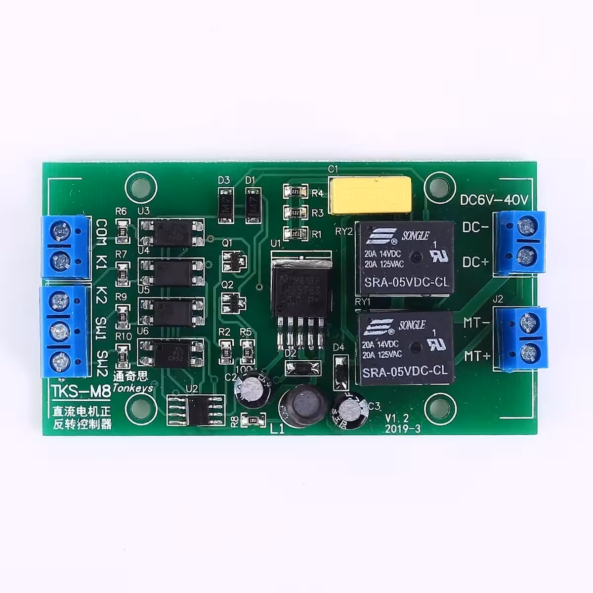
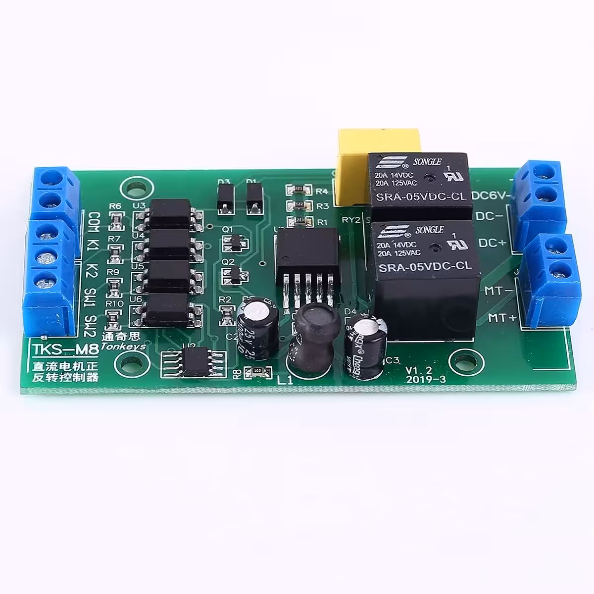
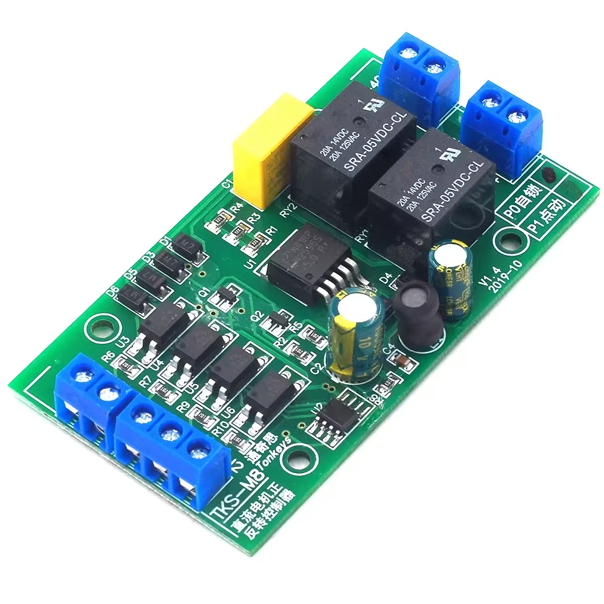
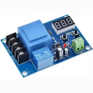
DC Motor Reversing Controller – Forward/Reverse control without the complex wiring
Working on a linear actuator, a reversible mechanism, or a custom DIY project that needs precise directional control? Usually, this would mean sourcing relays, transistors, and dealing with a mess of wires. This DC motor reversing controller simplifies everything into one compact, ready-to-use module. Just connect your power supply, motor, and switches, and you are up and running in minutes.
Note: The motor receives the same voltage as the power supply. This controller does not regulate or step down the output voltage.
Why choose this controller? (Key Benefits):
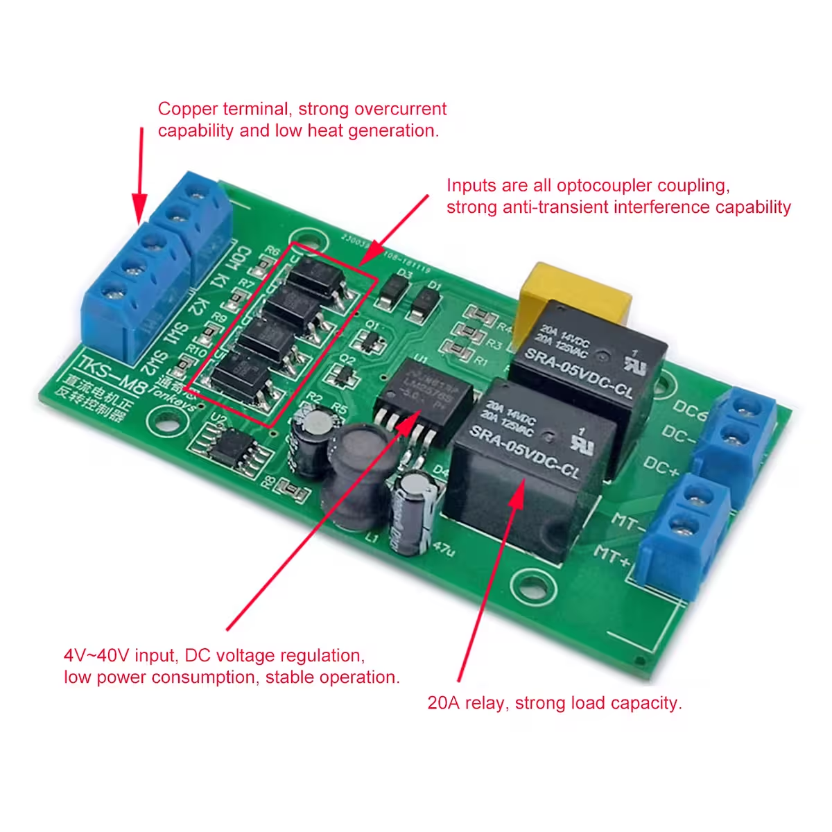
- Wide Voltage Range: 4–40V DC — Compatible with LiPo batteries, lab power supplies, or industrial adapters without needing adjustments.
- High Output Current: Up to 20A — Handles motors with high start-up surges, suitable for loads up to approximately 80W.
- Two Selectable Modes: PO and P1 — Choose between ‘Self-Locking’ (start with a short pulse) and ‘Jog’ (active only while the button is held) to suit your specific application.
- Universal Active-Low Inputs — Connect simple push-buttons, NO mechanical limit switches, or 3-wire NPN sensors directly, with no extra resistors or logic required.
- Integrated Limit Switch Inputs (SW1/SW2) — Automatically stop the motor at the end of its travel to prevent mechanical jams or overloads.
- Long Service Life: >150,000 cycles — Built for reliability in demanding, repetitive daily tasks.
- Low Power Consumption: 0.6W active / 0.1W standby — Highly efficient, ensuring minimal battery drain when the system is idle.
Performance and Technical Details
The controller is designed with active-low inputs: an input triggers when the voltage drops below 2V. This makes it fully compatible with standard push-buttons, NO (normally open) mechanical limit switches, and 3-wire NPN-NO sensors without needing intermediate components.
Response times are ≈20ms for K1/K2 commands and ≈50ms for SW1/SW2 limit switches — providing a perfect balance between rapid response and stability against false triggering.
Please note that recommended current capacity varies by voltage: at 12V, you can draw up to 20A, while at 24V, we recommend limiting the load to ~10A to ensure long-term thermal stability. Always use a properly rated fuse and cables suitable for your specific load.
| Parameter | Value / Detail |
|---|---|
| Operating Voltage | DC 4–40V (6–36V recommended) |
| Max Output Current | Up to 20A (at 12V) |
| Recommended Motor Power | Up to ~80W |
| Module Consumption (Active) | Approx. 0.6W |
| Module Consumption (Standby) | Approx. 0.1W |
| Input Signal Type | Active-low (triggers below 2V) |
| K1/K2 Response Time | ≈ 20ms |
| SW1/SW2 Response Time | ≈ 50ms |
| Operating Modes | PO (Self-locking) / P1 (Jog) |
| Service Life | >150,000 cycles |
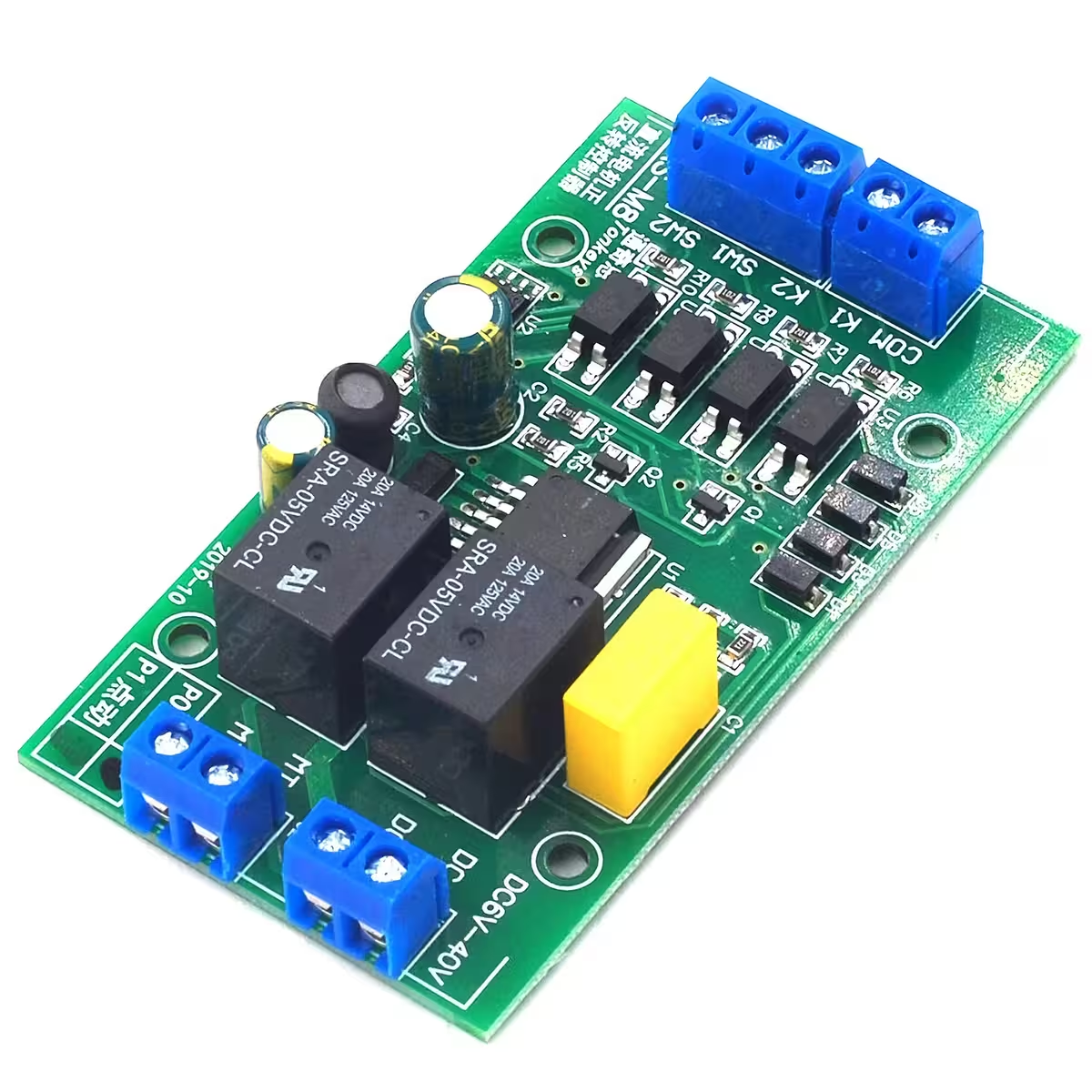
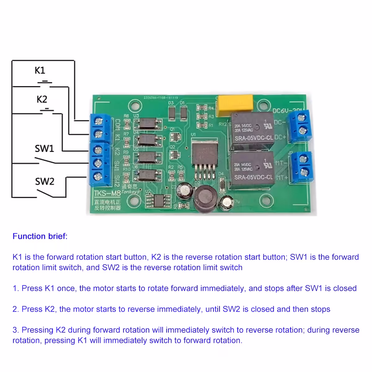
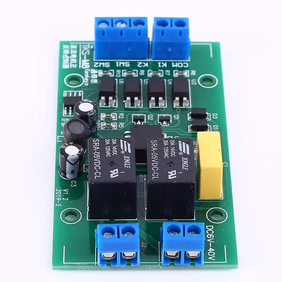
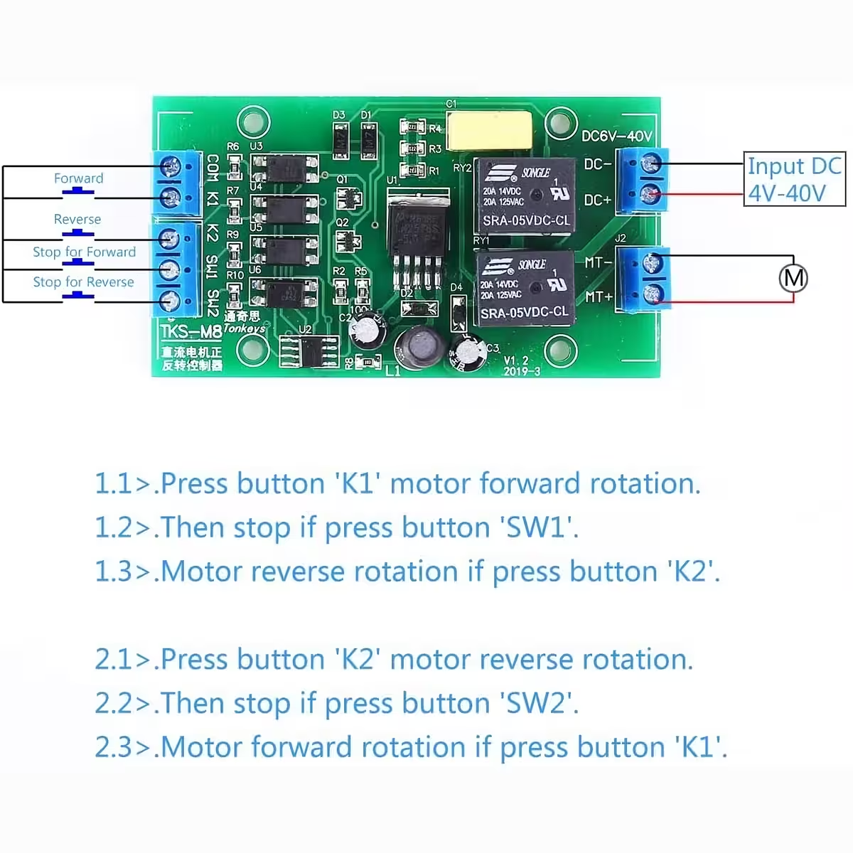
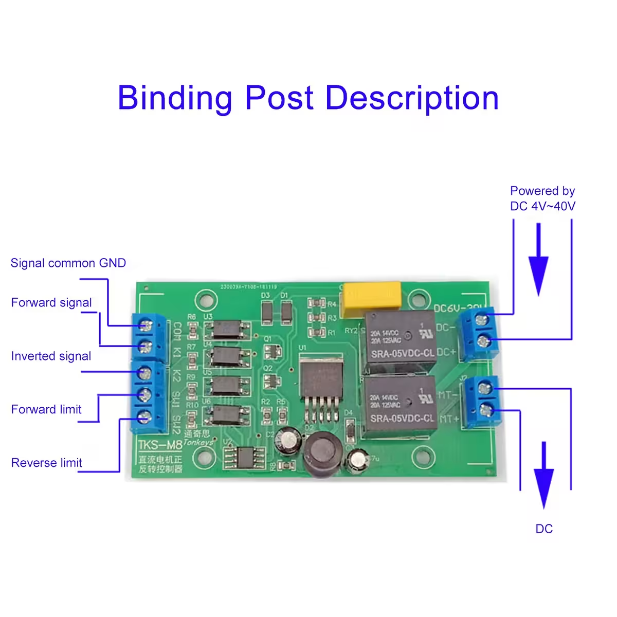
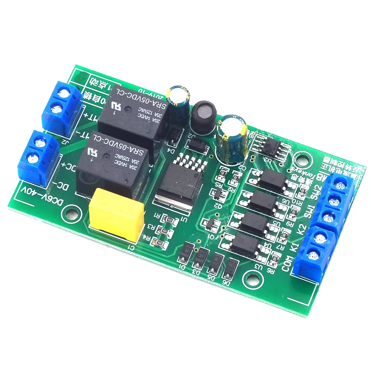
| K1 Input | Forward command (active-low) |
| K2 Input | Reverse command (active-low) |
| SW1 | Forward limit switch (NO recommended) |
| SW2 | Reverse limit switch (NO recommended) |
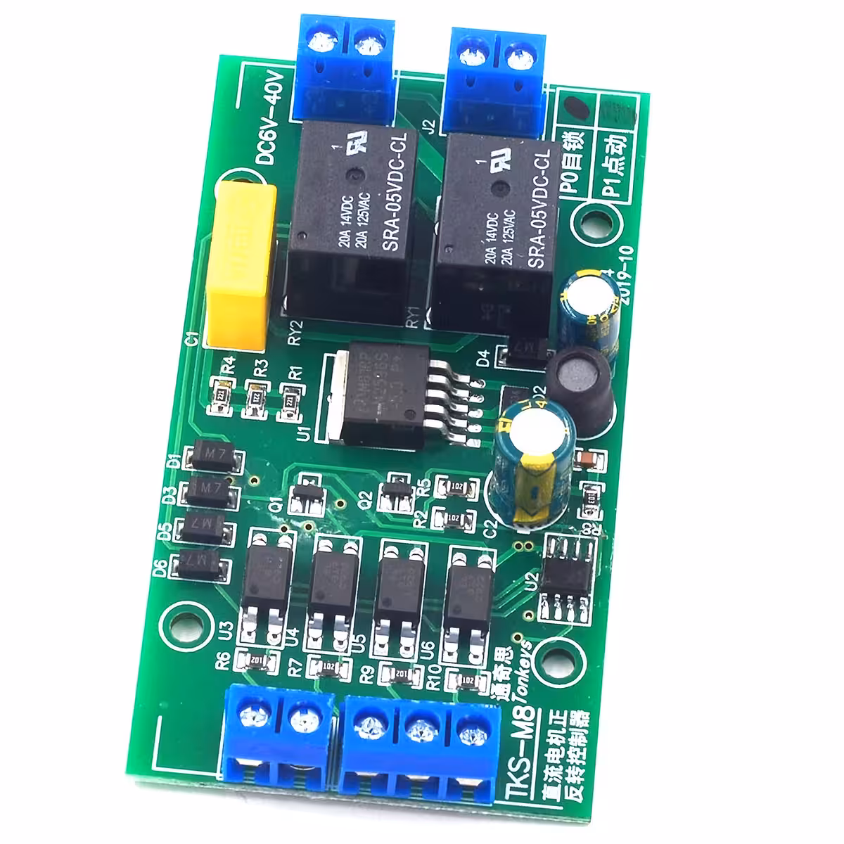
| VIN+ / VIN- | DC Power Input 4–40V |
| Motor+ / Motor- | DC Motor Output |
Programming and Usage Instructions
PO Mode (Self-locking): A short pulse on K1 or K2 starts the motor. It will continue to run autonomously until it hits the corresponding limit switch or receives the opposite command. Ideal for automated systems.
P1 Mode (Jog): The motor runs only as long as the K1 or K2 command is held active. Perfect for fine-tuning and manual positioning.
- Connect your power supply to VIN+ and VIN– (ensure correct polarity).
- Connect your DC motor to Motor+ and Motor–.
- Select your operating mode: PO for self-locking or P1 for jog.
- Connect your control buttons or signals to K1 (forward) and K2 (reverse) — these are active-low inputs.
- Optionally, connect your mechanical limit switches or NPN-NO sensors to SW1 and SW2.
- For automatic A→B→A cycling: Connect NO switches from position A to K1 and position B to K2, leaving SW1/SW2 disconnected.
- For Arduino integration: Connect the Arduino GND to the controller GND, and connect your digital pins to K1 and K2. Set pins as OUTPUT and write LOW to trigger.
- Always check your motor’s inrush current and install a suitably rated fuse on the power line.
Package Contents
- 1 × DC Motor Forward/Reverse Controller, PO/P1 modes
Frequently Asked Questions
What does ‘active-low’ mean?
The input triggers when the voltage drops below 2V, which happens when the pin is connected to ground (GND). This allows for direct connection of standard buttons, NO limit switches, and NPN sensors without needing extra resistors or logic gates.
What is the difference between PO and P1 modes?
In PO mode, a short pulse starts the motor, and it runs until it hits a limit or receives a stop/reverse command — great for automation. In P1 mode, the motor runs only while the button is pressed — ideal for manual control or precise positioning.
Can I connect this directly to an Arduino?
Yes. Simply connect the Arduino GND to the controller GND and use two digital pins set as OUTPUT. When the pin is set to LOW, the command is triggered. The Arduino handles the logic, and the controller handles the power.
Can I use NC (normally closed) limit switches?
This controller is optimized for NO (normally open) switches. NC switches will invert the logic and may cause unexpected behaviour. We strongly recommend using NO contacts for SW1 and SW2.
Do I need a heatsink for high current?
If you are operating near 20A or in intensive, continuous cycles, please ensure adequate ventilation. For heavy, continuous loads, adding a small heatsink or forced-air cooling will significantly extend the module’s lifespan.
How do I create automatic cycling without a timer?
Connect NO switches at position A to K1 and position B to K2, leaving SW1 and SW2 unconnected. When the motor reaches either end, the switch will trigger the opposite direction, causing the motor to oscillate continuously.
Product Video
Gallery


Reviews
There are no reviews yet.